LED Flasher: Click here to see the LED Flasher Units that we offer
So you want to install LED Turn Signals on your DR650. Well, not only do you need the signals, but they require a LED flasher unit as well. I recently did the entire conversion process and thought I would document the task and share the details with everybody! For this project I used the 12 volt LED Turn Signal Flasher and the Crash Advantage LED Turn Signals from our Dual Sport page.
- The first thing to do is remove both side covers and the seat.
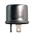
- With the seat off, you will be able to see the stock flasher unit on the right side of the motorcycle, just in front of the frame. Below is an image showing you just where it is.
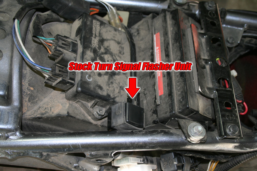
- Disconnect the wire connector from the flasher unit.
- The stock flasher is held by a rubber fitting that goes around the flasher and then attaches to a metal tab welded to the frame. Use a screwdriver to gently bend the tab up about 45 degrees so you can slide the rubber holder off the tab.
- STOP! The old LED Flasher we sold had 3 tabs for connections. If you have a 3 prong LED Flasher, drop down to the next step and follow all of the instructions. Should you have purchased your LED flasher from us recently, your flasher has just two connectors. You will need to cut the connector off and crimp the connectors provided with the LED flasher onto the two wires. Plug the brown/white wire onto the 'B' plug on the new flasher and the black wire onto the 'L' terminal. Zip-Tie the flasher to the metal tab that the old flasher was attached to. Congratulations, you are all done with that portion of the installation.
- With the stock rubber removed, slide the rubber holder for the new flasher (included) onto the flasher unit and then onto the same tab as the stock one, and then bend the tab back down in place.
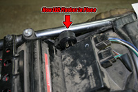
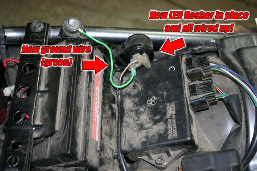
- The image below shows how the new flasher unit should look once you have it in place. I opted to position mine so that the three connector prongs were facing up so there was enough clearance for the connectors. Yes, there is plenty of clearance between the seat and flasher with it in this position.
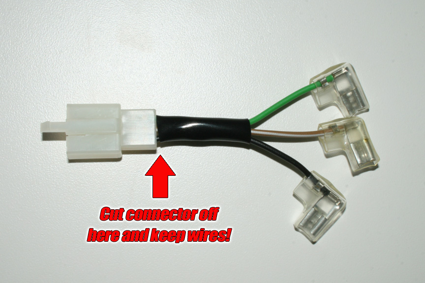
- The new flasher comes with a small three wire connector assembly (see image below). Cut the three prong plastic connector off right at the base, leaving you with three individual wires with a 90 degree female plug on each end. (Newer flasher units will only come with 2 female plugs to splice into stock wiring)
- Now cut the connector that went into the stock flasher off, leaving you a light blue and orange wire. Strip approximately 1/4 inch of wire off each end.
- Strip the same off of the black and brown/white wires with the 90 degree connector on the end.
- Slide a piece of heat shrink tubing (provided by you) over the orange and light blue wire.
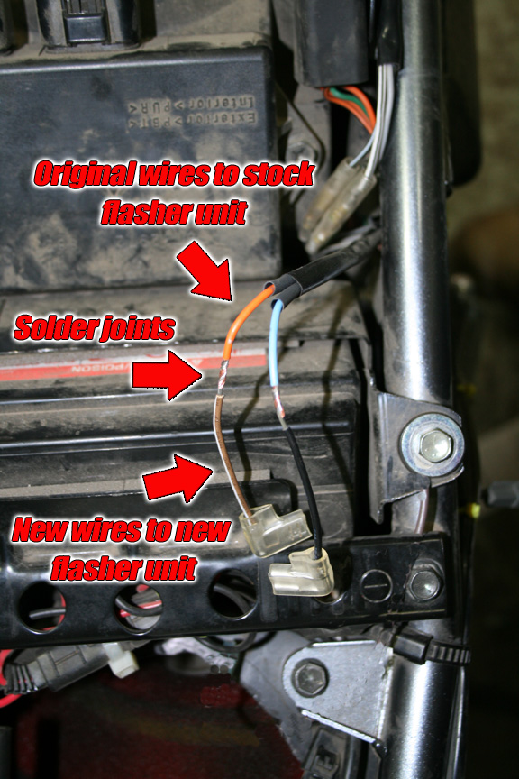
- Twist the brown/white wire to the orange wire and the black wire to the light blue as shown in the image below.
- Solder the two joints, pull the heat shrink tubing and shrink or wrap in electrical tape. See the image below to see how this should look.
- Now you can plug the brown/white wire onto the 'P' plug on the new flasher and the black wire onto the 'L' terminal.
- Included with the flasher is a single green lead as well with a hole terminal on the end. This is a ground wire that you need to connect or the flasher will not work. (I know, there wasn't one on the stock flasher, but the LED flasher has to have a good frame ground.) I put a straight terminal on the end of the wire so it fit nicer and then routed it over to the bolt for the battery cage as you see in the image below.
That is it for the flasher! Now you simply need to replace the turn signals themselves with LED units.
NOTE! Before you start installation of the signals, you must remove the indicator lamp in the dashboard to the right of the key. If you do not remove that, power will bleed back through this lamp and the LED flashers will not work when you test them! Simply reach under the dash and pull the entire plug out of the dash. Remove the lamp and plug the empty socket back into the dash. You will not need to leave it this way, though you can if you like. The second part of this installation covers how to correct this situation, but for now, please remove this bulb.
In the following examples, I have used our Crash Advantage turn signals. These flex at the stalk and are short enough to avoid being broken. If you use a different LED signal, the wire colors may be different, but the process would be the same. Remember that LED lights are polarity sensitive, if they do not work the way that you wire them up, flip the wires around before calling and telling us that they don't work.
I have done this installation two different ways. For the front, I soldered the wires from the new LED signals to the leads from the stock signals so that I could use the stock connectors going into the main wiring harness. (Best way to do it!) For the rear, I cut off the stock connectors and so the images show creating new connectors to the main wiring harness. (Works fine, but not best way to do it in my opinion, but it allows you to keep the stock signals intact and sell them to pay for part of your LED conversion, as I did!)
- In the front begin by removing the headlight cowling/number plate. There is a screw in each side and a single bolt in the center right above the fender.
- Undo the tie-wrap around the plastic just on top of the headlight. DO NOT CUT! This is a reusable tie-wrap. Just lift the little tab on the wrap and pull it apart, you will need it again when done.
- Undo the velcro tabs on either side of the plastic wrap to expose the wires inside.
- Follow the wires from the signals to their connectors and lift the tab and gently pull this connection apart.
- Unbolt the stock front signals from their mounts and gently pull the wires out through the nut and the bracket.
Now you need to decide if you are going to use the stock connectors or install new ones. If you are going to use the stock connectors, continue below. If you are going to use your own connectors, skip to the next section.
- Wise decision to use the stock connectors. That really is the way to go. Slide the plastic covering all the way back up to the connector and then cut the wires off the stock signals approximately 2 inches from the where they come out of the signal stalk. Put the stock signals away in a box or round receptacle!
- Slide about an inch of the black protective wrap off of the wire and cut that off. You need to do this to make room for the splice to the new signal wires.
- Install the new LED signals.
- Cut the wires coming out of the new LED signals about 2 inches from the stalk.
- Strip approximately 1/4 inch of insulation off all 4 wires.
- Slide a piece of shrink wrap tubing around just one of the wires for each connection.
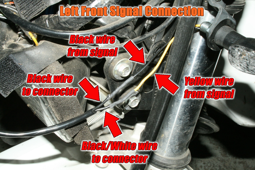
- Twist the wires together (Yellow to Black/White and then Black to Black) turn on the key and make sure that every thing works, then solder this joint together. (Remember you have to have the plug connected for them to work!)
- Slide the shrink wrap over the soldered connection and heat it with a heat gun until it has shrunken up nice and tight.
- Slide the protective tubing down over the joint and there you have it! See the image below for some help!
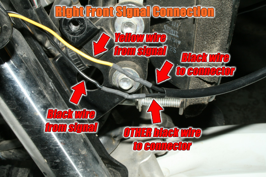
- Below is an image of the installation on the right side.
OK, so you decided to just hack off the stock connectors and go from there. That is fine too!
- First thing is that you will need either female connectors to go with the male connectors that come on the signals, or entirely new connectors of some kind to your liking. You can find connectors at almost any auto parts store.
- You can shorten the leads up if you like or keep some slack in the system, that is up to you. You want to use some type of removable connector though to be sure that you can easily remove the blinkers someday should you need to.
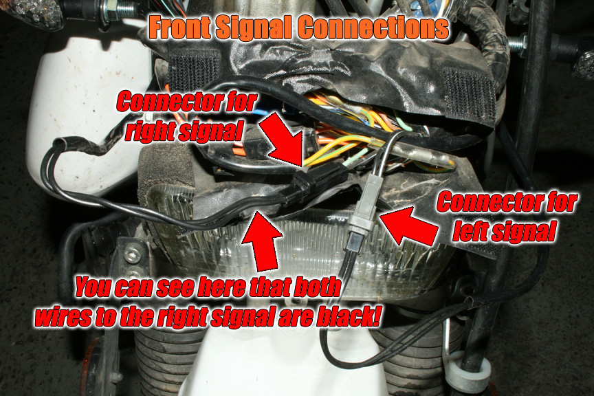
- Follow the color code as (Yellow to Black/White and then Black to Black) shown in the image. Be sure to test before committing!
- Installation for the right signal is basically the same as whatever you did for the left. The only twist is that BOTH of the wires coming from the connector are black! You must twist them together and test them before soldering to be sure they are correct. (Again, remember to plug in the connector before testing and be sure that the dash indicator light is out!)
Below is a shot of the wires all tucked in and ready to have you put the plastic wrap on secured by that tie-wrap you took off. Then put the cowl back on with all three screws and lets go to the rear and get that done!
Front is all done and now we will move on to the rear signals.
- You can go with either the stock connectors or use your own just like the front. If you use your own connectors, you are going to need to have extensions so the wires will reach the junction clear up under the side panel.
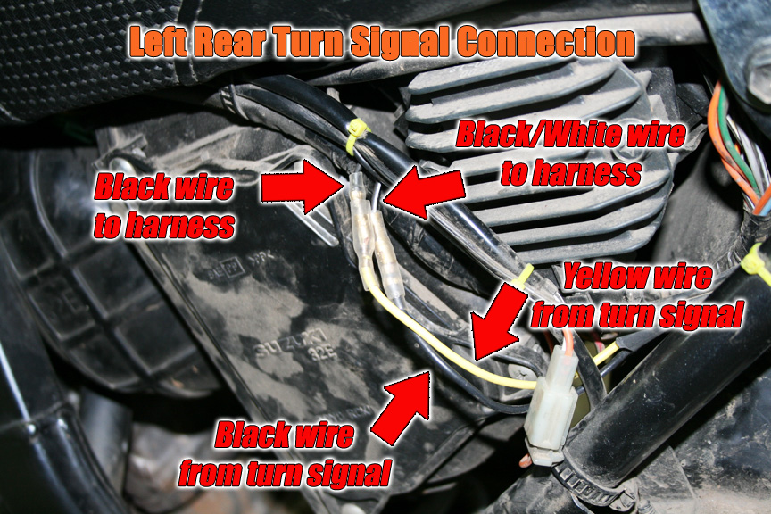
- As you can see in the image below, just like the front, I soldered extensions onto the Yellow and Black wires from the turn signals. I made them long enough so that they would go all the way to the where the stock connectors were.
- I then placed some split tube around the extended wires to protect them, though you can't really see that.
- Since I no longer had the stock connectors, I cut them off on the wiring harness side and installed a female connector on the Black/White wire and a male connector on the Black wire side. This would stop you or somebody else from plugging the wrong wires together.
- Below is an image of the left rear connections for reference.
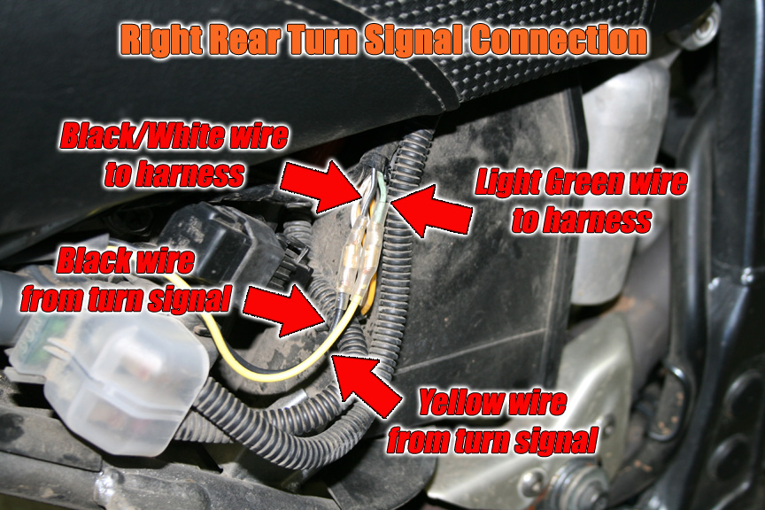
- Follow the same three steps as above for the right side rear signals. Image below shows completed installation for the right side.
Now that you have completed the installation, turn on your key and click the signal switch to either side to test. Click here to read step 2 of this procedure that covers the installation of the diode kit to stop the bleed-over and allow you to put the indicator bulb back in.
LED Flasher: Click here to see the LED Flasher Units that we offer