Follow up:
While this modification does produce more peak power you still have to monitor system voltage if you are feeding additional accessories. One drawback is that the stock stator will produce enough power to charge the battery at idle. The modified stator needs 1800-1900 RPM to get over the break even point. This mod was documented many years ago when high output stators for the DR650 did not exist. The currently available aftermarket stators put out as much additional power and do it in the same RPM range as the stock stator. A high output aftermarket stator is a better solution to the need for more electrical power than performing the wye-to-delta modification.
Many of us would like a little more electrical capacity from our DR650s. I did some testing recently and determined I could power an additional 70 watts of lights/accessories and still keep the battery voltage high enough to stay charged. It's good to know where this limit is but I want enough power for more light, heated grips and a heated vest.
Since there isn't an aftermarket high output stator available for the DR650 I started doing some research about do-it-yourself rewinding. I figured I would get a used stator to practice on and see if I couldn't wind a little more power out of it. So I found a used stator, cleaned it up and started to take a real close look at how the thing is wound. Well, after a couple of hours making notes and drawings I realized I wasn't going to really figure it out without unwinding it. One complication is that the ignition charge coil is wound on after the charging system coils. Most street going motorcycles don't have an ignition charge coil. They power the ignition system from the battery. This can be a blessing for us DR650 riders. The charge coil will still power the ignition even if the battery is totally dead giving us the option of a push start. Most other street going motorcycles have to have some life in the battery to run at all and will run poorly with a low battery. A DIY rewind was starting to look like more trouble that it was worth.
There's a great thread on ADV - Stators demystified - that gave me some inspiration for a new project. It turns out that most 3-phase motorcycles are 'Wye wound'. If a wye wound stator is reconfigured into a 'Delta wound' arrangement the output current can increase by about 40%. Ah Ha! The light bulb blinked on! I could just reconfigure my stator from wye to delta and have more power.
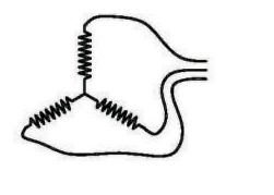
A wye wound stator is just what it sounds like. It's wound in the shape of a Y:
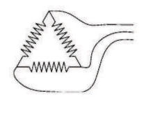
A delta wound stator has the coils connected in a triangle:
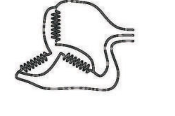
On paper it's pretty simple to reconfigure the wye to a delta. Just cut out the point where all three coils are connected together and reconnect them end to end:
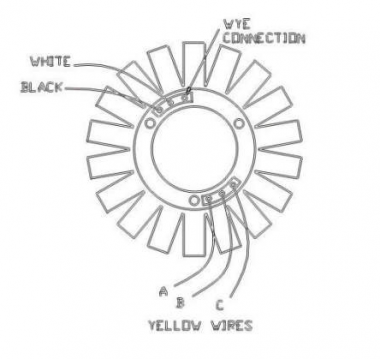
The stator connections are arranged like this:
The black and white wires are for the ignition charge coil. They come out of the motor and go to the CDI box. A, B and C are the yellow wires that come out of the motor and go to the voltage regulator. I cut the 3 wires from the wye connection terminal, extended them and reconnected them one to each the of the yellow wire connections. It doesn't matter which one connects where except you must not connect the wye end of a coil to it's own yellow wire connection.
With the modified stator installed in the bike it was time for testing. I was able to run 2 additional H4 bulbs on high beam (60 watts each) for 120 additional watts and still keep battery voltage over 13 volts. That will give me just enough power to run brighter lights and heated gear all at the same time. Any more load causes the system voltage to slowly drop.
One concern is whether the stock voltage regulator will handle the additional power. One thing I learned in my initial research is the regulator works by shunting extra output to ground. The stator is always putting out as much power as it can at any given rpm. Some of that power is drawn off by the battery, lights, etc. Any 'extra' is shunted to ground by the voltage regulator and is dissipated as heat through the regulator and the stator coils. So using the extra power actually takes some of the load off of the regulator and stator.
I'm pretty happy with the results. A good voltmeter is a must if you plan to run additional electrical accessories near the limit of the system.
This modification is not limited to DR650s. Since most 3-phase permanent magnet motorcycle alternators are wye wound this could be done to many other bikes.
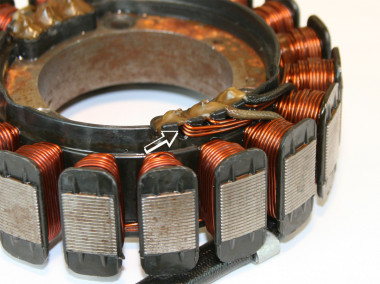
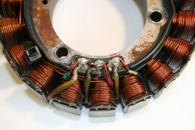
- Here is where you will find the Wye connection terminal
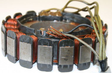
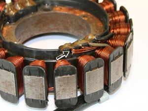
- Cut the three wires away from the terminal connection
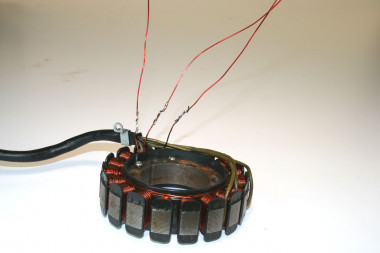
- I extended the cut wires with 19ga copper magnet wire
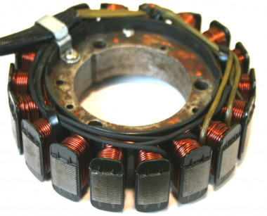
- Since I don't expect the varnish on the magnet wire to hold up to exposure to hot motor oil the extended wires were covered with some black fiberglass tube. The new wires were routed along the stator windings and over to the yellow wire connection terminals and secured with zip-ties.
- I chipped the epoxy away from the terminals where the yellow wires are attached. The new black sheathed wires were routed between the stator poles and soldered in. It doesn't matter which terminal each wire is connected to as long as you don't make a connection that loops back on itself. I used an ohm meter to identify matching wire ends and then color coded the wires and the terminals red, green and gold so I wouldn't accidentally connect one wire in a separate loop. Look closely and you will see the wire marked with gold is connected to the terminal marked red. Red is connected to green and green is to gold. After soldering I gave these terminals a fresh coat of epoxy.
